|
ELASTIC
MODEL
Hubbert and Willis (1957) developed the first realistic model
relating the recorded hydraulic fracturing test variables
to the in situ state of stress in rock.
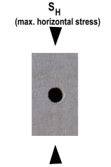
At
the borehole wall the tangential stress at the two points
aligned perpendicular to the minimum horizontal stress, Sh,
will be the first to meet this criterion as the test-interval
pressure is raised. A hydraulic fracture will thus initiate
and extend in the direction of the maximum horizontal stress,
SH.
With
these assumptions, Hubbert and Willis (1957) were able to
obtain an elastic solution relating the hydraulic fracturing
initiation pressure Pc (also called critical or
breakdown pressure) and the two principal horizontal stresses,
Sh and SH.
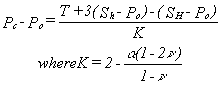
where
T is the tensile strength of the rock.
In
their paper, Hubbert and Willis assumed that T is negligible
at great depth because of preexisting fissures traversing
the rock and did not incorporate it in the above fracturing
criterion .
Hubbert
and Willis suggested that the least horizontal stress is equal
to the wellbore pressure required to extend the hydraulic
fracture while holding it open. Kehle (1964) was more precise
about the magnitude of Sh and suggested that it
was equal to the shut-in pressure, Ps, or the minimum
pressure needed to keep the fracture open against the fracture-normal
stress (equal to Sh) after pumping has been stopped:

Thus,
knowledge of four test variables (Pc, Ps,
Po and T) is required to calculate the two horizontal
principal stresses provided the above assumptions hold.
To
avoid the need for determining T, one of the most ambiguous
rock mechanical properties (Hudson and Fairhurst, 1969), Bredehoeft
et al. (1976) suggested replacing the breakdown pressure Pc
with the fracture reopening (or refrac) pressure, Pr,
obtained in subsequent pressurization cycles. Under the assumption
that the hydraulic fracture closes completely between pressurization
cycles and that the state of stress around the borehole thus
returns to its pre-test condition, equation Hubbert and Willis
equation reduces to:
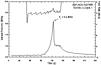
Typical
Hydrofrac Pressure-Time Record
|
Top |
POROELASTIC
MODEL
One
of the simplifying assumptions made in the elast model is
that no injected fluid penetrates into the surrounding rock.
This condition may be correct in oil wells lined with impermeable
mud cake, but certainly inaccurate in clean open holes of
the type commonly used for stress measurements. The radial
outward flow of the injected fluid into the rock pores creates
an additional stress field around the borehole. Haimson and
Fairhurst (1967) invoked the theory of poroelasticity (Biot,
1941) to incorporate the effect of the injection fluid permeation
on the stress distribution around the borehole, and obtained
the following hydraulic fracturing criterion:
a
is the Biot poroelastic parameter (Biot and Willis, 1957),
and is defined as a = 1 - Cr/Cb,
where Cr is rock matrix compressibility and Cb
is rock bulk compressibility; n is the Poisson's ratio
for the rock.
|
Top |
FRACTURE
MECHANICS MODEL
Conventional
elastic and poroelastic criteria assume that the rock subject
to hydraulic fracturing behaves as a continuous medium. However,
the presence of natural cracks in the test interval may violate
this simplifying assumption. Abou-Sayed et. al. (1978) introduced
a fracture mechanics approach to the hydraulic fracturing
criterion assuming the existence of arbitrarily oriented cracks
in rock. Further assuming that there is always a symmetrical
double crack of length a (typical of the rock type)
which extends from the hole wall in the direction of SH.
Rummel and Winter (1983) and Rummel (1987) derived a fracture
mechanics solution that can be used to calculate SH.
They suggest that hydraulic fracturing will occur when the
mode I (opening) stress intensity factor KI at
the tip of the crack reaches a critical value (fracture toughness
KIC). The peak pressure Pc recorded
on the pressure-time plot is then interpreted as equal to:
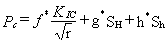
where
f*, g*, h* are dimensionless
stress intensity functions calculated in terms of the normalized
crack length a/r, where r is the radius
of the borehole. For comparison with the classical elastic
solution (Hubbert and Willis, 1957) the first term of the
equation f*KIC/Ö r
is equivalent to the apparent hydraulic fracturing tensile
strength of the rock.
|
Top |
HTPF
A
novel approach to calculating in situ stresses from hydraulic
fracturing data has been proposed by Cornet and Valette
(1984). It is the Fracture Pressurization Method, originally
called 'hydraulic tests on preexisting fractures' (HTPF)
by Cornet (1986). By using the general theory of stress
in 3-dimensional space, the fracture-normal stress can be
formulated as a nonlinear function of depth and fracture
orientation, expressed in the form of 6 unknown parameters
which uniquely define the stress tensor. Unlike the conventional
models, the fracture pressurization method neither invokes
the stress-strain relations nor assumes the idealistic (homogeneous,
isotropic, and linear elastic) rock properties. The only
assumptions made where the fracture pressurization criterion
is used are:

Under
these assumptions, the state of stress at depth D can be
represented by the following tensor (Cornet and Valette,
1984):
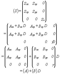
where
g is the mean weight density of the rock; D is the
depth; (S) is symmetric with four independent components;
(A) is the stress tensor at the surface (D=0); and (B) is
a tensor representing the linear variation of the stress
components with depth. McGarr (1980) had shown that the
stress linear relationship with depth is a direct result
of the equations of static equilibrium when the horizontal
stresses are uniform over large area.
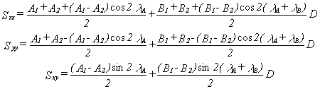
Using
the definitions in the above equations A1 and
A2 are the principal horizontal stresses at the
surface (D=0). Denoting the direction of A1 with
respect to north as l A,
eigenvalues of (B) as B1 and B2, and
the direction of the eigenvector corresponding to B1
with respect to A1 as l B.
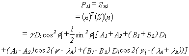
Then each normal (i=j) and shear (i¹ j) stress component
Sij (i,j=x,y) can be related to the six unknown
principal components A1,A2,B1,B2,l
A
and l B
by (Jaeger and Cook, p. 24-26, 1976):
The
measured attitude (dip f i,
dip direction y i)
of the pressurized fracture defines the unit normal vector
(n) of each fracture-normal stress Sn,i across
ith fracture, measured by the respective shut-in pressure
Ps,i can be related to each stress component
of (S):
By
conducting a minimum of six pressurization tests in separate
intervals within the same stress regime, the six unknown
parameters (A1, A2, B1,
B2, l A
and l B)
in the fracture-normal stress equation can be determined,
using one of several available least squares techniques.
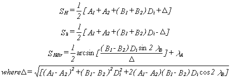
The six parameters completely define three independent components
(Sxx, Syy, Sxy) of horizontal
stresses as a function of depth. Thus, the horizontal principal
stresses and their directions are calculated as follows:
|